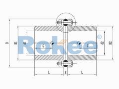
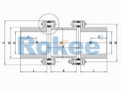
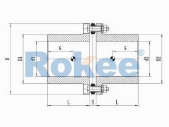
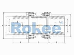
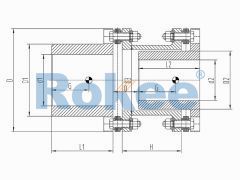
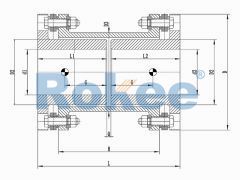
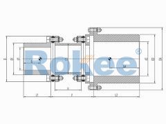
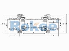
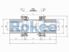
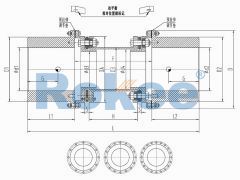
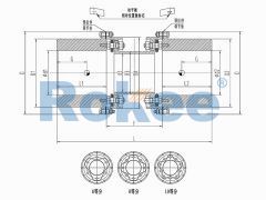
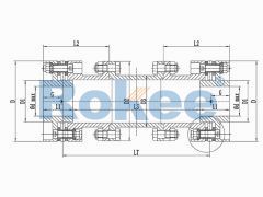
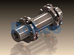
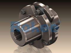
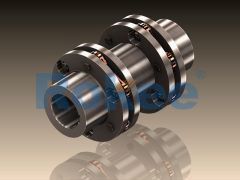
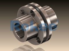
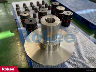
Flexible Diaphragm Coupling Structural Diagram
Rokee is a Diaphragm Coupling Manufacturer from China, design & custom-made diaphragm coupling with reasonable price and high-end quality, learn more about flexible diaphragm coupling structural diagram information, please email us, Rokee's technical engineer will reply as soon as possible.
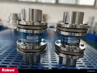
Diaphragm Coupling is a kind of high-performance metal Flexible Coupling, which compensates axial and angular displacements by the deformation of elastic diaphragm while transferring torque. It features with compact structure, large transmission torque, long service life, maintenance-free, high temperature resistance, acid and alkali resistance, and corrosion resistance, suitable for shafting transmission in high temperature, high speed and corrosive environment.
Rokee's RL series Steel Laminae Couplings are independently developed on the basis of high-quality products from Europe and Japan. It has smaller volume, larger torque of the same type, more reasonable proportioning size, large compensation range, light weight and small moment of inertia. Special elastic gasket design is adopted in the hole connection part of bolt and diaphragm group, which greatly reduces the stress concentration in the hole edge part, eliminates the tear loss of diaphragm, and extends the service life. With modular design, the coupling assembly is simple and its maintenance and replacement are quick. The performance far exceeds the national standard JM series products, which are widely used in fan systems, steam turbine units and other important industrial fields.
RLM Small Single Diaphragm Coupling
The RLM standard single section small metal diaphragm coupling is suitable for various industrial process pumps and small torque working situations with a working speed not exceeding 5000rpm, and cannot compensate for radial errors.RLMD Small Double Diaphragm Coupling
The RLMD standard double section small metal diaphragm coupling is suitable for various industrial process pumps and small torque working occasions with a working speed not exceeding 5000rpm.RLA Standard Single Diaphragm Coupling
The classic design of metal flexible diaphragm couplings is a reliable choice for medium to low speed applications, but cannot compensate for radial deviation.RLAD Standard Double Diaphragm Coupling
The classic design of metal flexible diaphragm couplings is a reliable choice for medium to low speed applications.RLAR Single Shaft Sleeve Reverse-mounting Diaphragm Coupling
Single side shaft sleeve reverse installation design, suitable for occasions with limited shaft head distance.RLARD Double Shaft Sleeve Reverse-mounting Diaphragm Coupling
The double-sided shaft sleeve reverse installation design is also applicable in situations where the distance from the shaft head is limited or the additional bending moment is smaller.RLAF Large & Small Shaft Mounted Diaphragm Coupling
The size difference design of the bilateral shaft sleeve is suitable for situations where the diameter difference between the two ends of the shaft is significant.RLAT Super Long Wheelbase Diaphragm Coupling
Adopting an intermediate shaft design, suitable for ultra long shaft spacing power transmission applications.RLQA No Flange Quick Installation Metal Diaphragm Coupling
Suitable for various industrial process pumps, fans, and other medium to low speed applications, with a maximum speed generally not exceeding 25000 rpm. It meets the requirements of API610/ISO14691 and is one of the first products for API applications.RLQF Flange Type Quick Installation Diaphragm Coupling
Suitable for drum pressure fans, turbine compressors, and other high speed applications, with a maximum speed of up to 35000rpm.RLQU Improved Flange Quick Installation Diaphragm Coupling
The improved RLQF has smaller additional bending moments and better performance. Suitable for drum pressure fans, turbine compressors, and other high speed applications.RLHD High Speed Diaphragm Coupling
Suitable for higher speed applications, it also adopts a flexible component integrated assembly design, with a maximum speed of up to 42000rpm.
JMIIJ Diaphragm Coupling
JMIIJ metal diaphragm coupling is designed with intermediate shaft, suitable for long distance transmission. Besides, the semi-coupling sleeve at both ends have no counterbore.JMII Diaphragm Coupling
JMII metal diaphragm coupling also adopts the single-piece design but has no counterbore, suitable for short distance transmission, with more compact structure.JMIJ Diaphragm Coupling
JMIJ metal diaphragm coupling is designed with intermediate shaft, suitable for long distance transmission. Besides, the semi-coupling sleeve at one end has a counterbore, facilitating the fixing of the shaft end.JMI Diaphragm Coupling
JMI metal diaphragm coupling adopts the single-piece design, suitable for short distance transmission. Besides, the semi-coupling sleeve at one end has a counterbore, facilitating the fixing of the shaft end.
Flexible Couplings are one of the major types of couplings. They find use to connect two shafts, end-to-end in the same line to transmit power that is torque from one shaft to another, thereby causing both to rotate in unison, at the same rpm.
The purpose of a Elastic Coupling is to transmit torque from one piece of rotating equipment to another, while accepting at the same time a small amount of misalignment. Flexible coupling misalignment is expressed, as an order of magnitude, in thousandths of an inch. Actual misalignment, expressed in coupling terms, is angular in nature and expressed in angular units, that is, degrees. How much misalignment is a function of the coupling type and installation. An installation variable is the equipment movement due to the temperature changes taking place in the machines as they go from the non-operating state to operation. Some angular values will be used in the discussion of the various types, but, again, these are for reference only. Each application must be reviewed using the type of coupling selected and the specific design proposed by the vendor.
« Flexible Diaphragm Coupling Structural Diagram » Post Date: 2023/11/14
URL: http://games.editingderrick.cn/en/blog/flexible-diaphragm-coupling-structural-diagram.html
Tags: Diaphragm Couplings, Elastic Diaphragm Couplings, Flexible Diaphragm Couplings, Double Diaphragm Couplings,
- Low Torque Dual Diaphragm Coupling
- Types Of High Torque Diaphragm Couplings
- Advantages Of Water Pump Diaphragm Coupling
- Single Diaphragm Coupling Agent
- Size Chart of Flexible Diaphragm Coupling
- Expansion Diaphragm Coupling
- Type Of Diaphragm Coupling For Transmission Seat
- Gear Corrosion-resistant Diaphragm Coupling
- Flexible Diaphragm Coupling Tagging
- Custom Expansion Type Diaphragm Coupling
